Find simulator. Google:
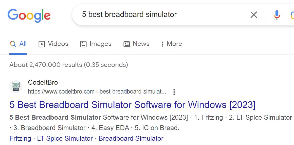
Choose Nr 3. (why?) Nr 1 is not a simulator, Nr 2. have nothing to deal with breadboards
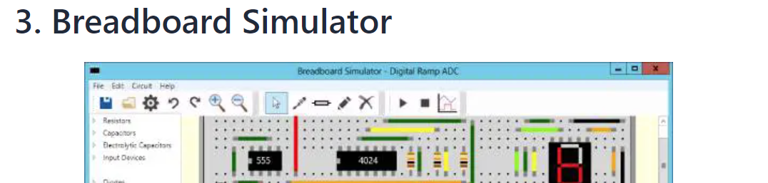
Get this free breadboard simulator software here.
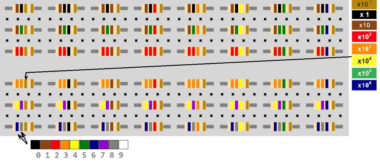
Learn Resistor strip code used in simulator (slightly differs)
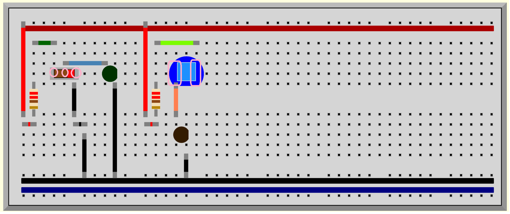
First impressions: buttons, switches, LEDS:
Inouts: SPDT switch means Single Push Double Throw (so it's classical one pole thumbler with 3 contacts. Push switch means Momentary Push button with contact zones shown below:
The biggest inconvenience is that the wires should only be drawn strictly vertically, or strictly horizontally. Therefore, in order to be able to draw at least something, enough space should be reserved for 90-degree turns of the connections.
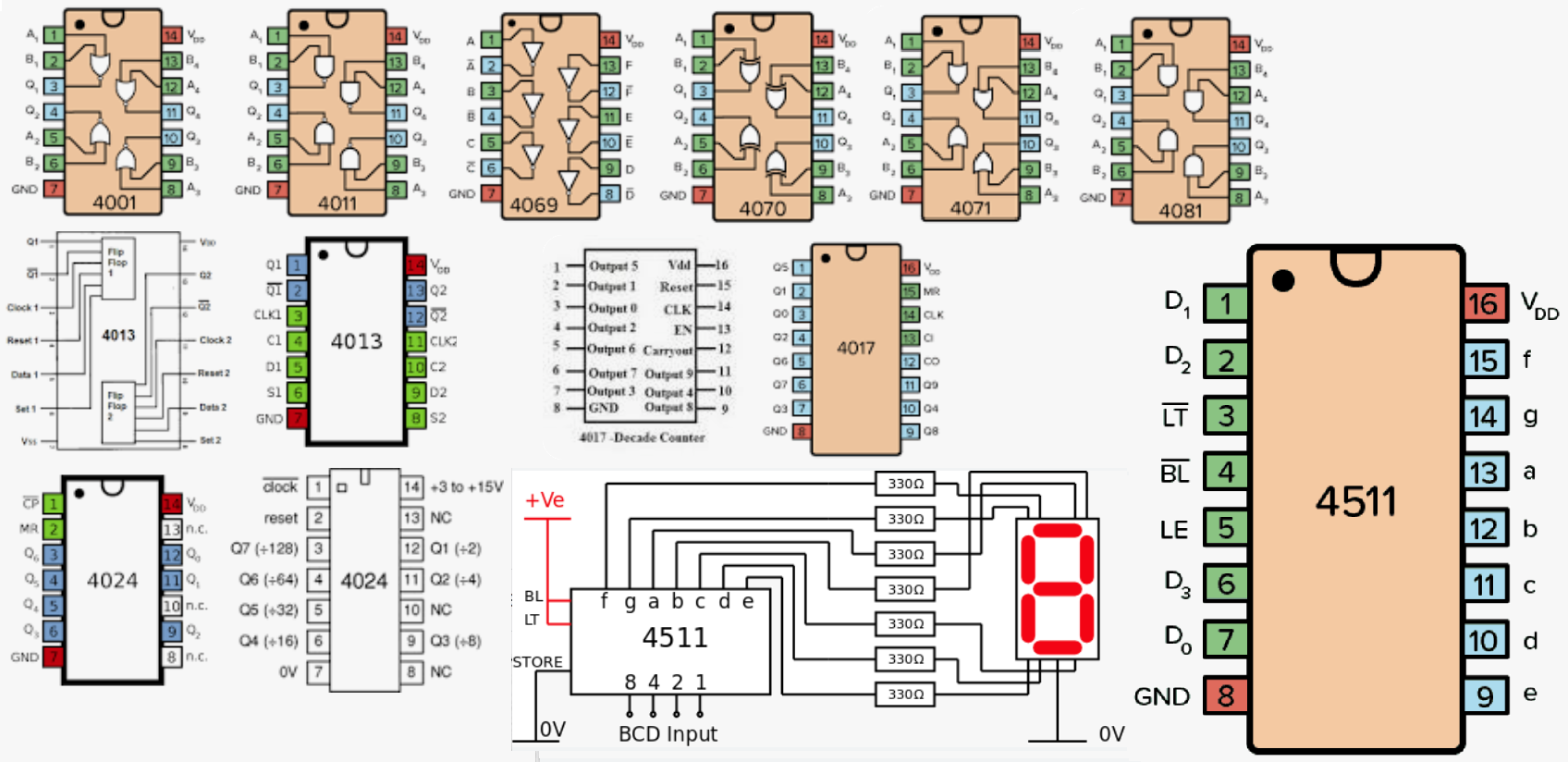
Built in digital IC-s:
4001 NOR  (Peirce's base)
4011 NAND (Sheffer's base)

4070 XOR  (Zhegalkin's base)
4081 AND

4069 NOT  (Boole's base)
4071 OR
4081 AND

4013 D-flip-flop
4017 Decade Counter
4024 Binary Counter
4511 Display Decoder
Use Output Devices -> Oscilloscope Probe to see time diagrams:
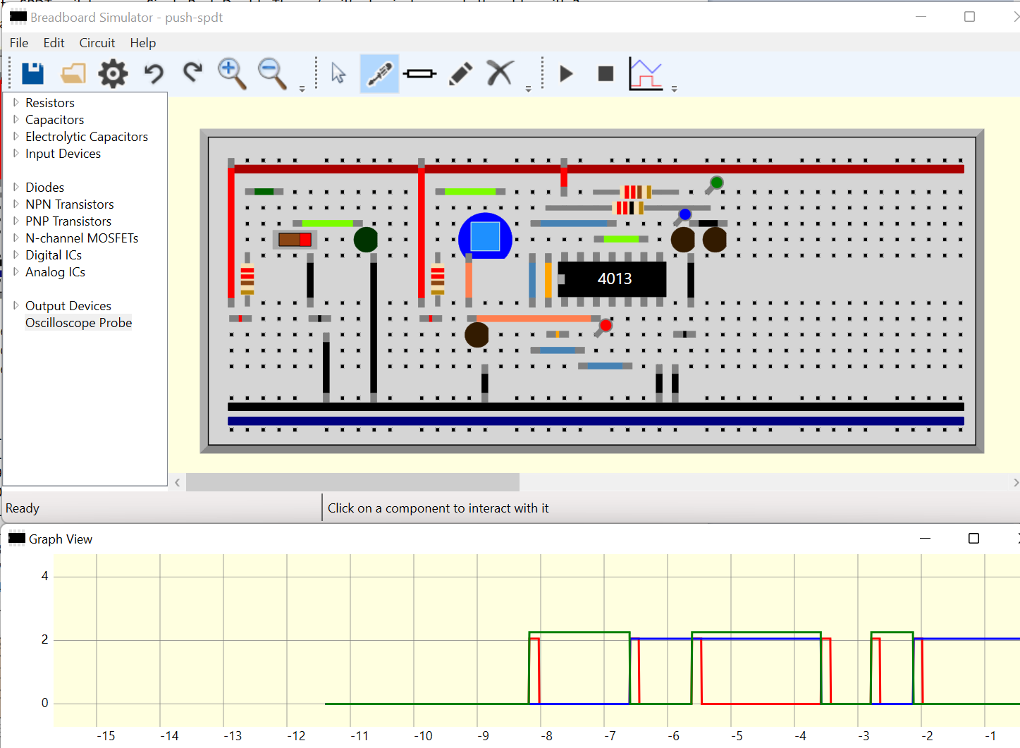
First attempt shown above (2-bit binary counter) can be downloaded here:
Further development:
-
port github sources to dotnet on linux or tk/python
-
add new components
-
..
-
repeat the fate of Elbrus (best case)